Fiber optic cables are a type of cable that can be made up of pure silica, doped silica, glass composite or plastics. Fibers made from pure or doped silica have the best characteristics for telecommunications. Glass composite or plastic fibers have high attenuation and low bandwidth, and are used in short distance, low transmission rate, and lighting systems.
Independently of what material they’re made up from, these cables transmit data over long distances using light signals. They offer several advantages over traditional copper cables, including higher bandwidth, faster speeds, and greater reliability.
The manufacturing process of fiber optic cables involves several key steps:
Usually, we start with a silica tube, made from the raw material (silica) and already with the physical characteristics of the optical fiber to be produced (density). This tube will give origin to the Cladding.
The core of this silica tube will be filled with gases that, when heated, solidify and form the core. After filling the core, the silica tube will originate the glass preform, which is the silica tube with the interior already processed.
There are 4 manufacturing processes for the glass preform:
MCDV is the most common, so we will only talk about this one.
|
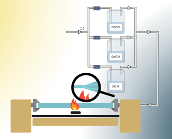
Inside the silica tube, chloride gases (SiCI4, GeCIe and POCI3) will be injected in controlled concentrations for the final objective. These gases will form the fiber core. The tube is rotated on its axis and heated to 1500 degrees. As the gases are injected, they form deposits on the inner walls of the tube. The amount and density of injection of these gases depends on the type of fiber being built. |
|
After all the layers of gases have deposited on the inside of the tube, the tube is closed, creating the glass preform.
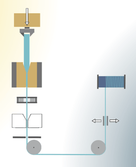
2. Drawing:After testing, the glass preform goes to the draw tower. In this process, the glass preform is placed in a vertical tower and fed into an induction graphite furnace that is heated to approximately 2000 degrees. At this temperature the glass becomes malleable enough that when the Glass Preform is pushed through the furnace the fiber flows through the tower, a diameter gauge controls this process. |
|
After this process the optical fiber receives its first insulation, Coating.
This Coating can be of various materials depending on the cable application:
Other possible materials in Coating: Acrylate Coating, Polyimide, Carbon, Polyetheretheerketone (PEEK), Polybutylene terephthalate (PBT), Polypropylene (PP), Polyethylene (PE), LSZH Low Smoke Zero Halogen (PE-PP), Polyvinylchloride (PVC), Polyvinylidene Fluoride (PVDF), Polyurethane (TPU), Halogen free Flame-retardant Polyurethane (HFFR), Hytrel (TPE), Ethylene tetrafluoroethylene (ETFE), Perfluoroalkoxy Teflon (PFA).
The number of fibers in a cable is another aspect that influences cable construction. There’s two ways the fibers can be inside the cable:
Whether in tight buffer or loose tube, to build the cable we have to group the fibers.
|
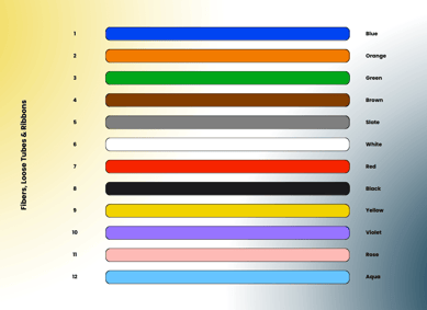
There are 12 standard colors that identify the fibers within the cable. If the cable has more than 12 fibers we need to make subunits to keep all the identified fibers. With the fibers grouped and identified, the next step is to choose the use of the cable: Indoor or Outdoor. |
|
With the cables for indoor use, the jacket is designed to cause the least damage to people in case of fire. They produce little smoke, and are free of materials that produce toxic gases when burning (fluorine, chlorine, bromine and iodine). Thus, the indoor cable is LSZH (Low Smoke Zero Halogen) rated.
In contrast to Indoors, outdoor cables are produced with other concerns: exposure resistance to the environment, humidity, temperature changes, impacts, and UV rays from direct exposure to the sun, animals, etc. Outdoor cables need tensile strength to be pulled over long distances, high resistance to stretch in the case of self-supported cables, high resistance to rodents and other animals in ducted or buried cables, and several other characteristics depending on the installation site.
After the glass preform goes through the draw tower and becomes optical fiber, it is subjected to a series of mechanical, optical and geometrical tests.
The first test is the tensile strength. In this, the fiber must withstand at least 7000kg/cm². After passing this test, the fiber is placed on reels.
Once on the reels, the fiber is subjected to a series of optical tests such as attenuation (power meter) and attenuation uniformity along the fiber (OTDR). The multimode fiber is also tested in bandwidth and numerical aperture (NA) that controls the number of modes that the fiber admits.
Geometric tests include core, clad, and coating diameters, non-circularity, and core/clad offset.
Overall, the fiber optic cable manufacturing process is complex and requires specialized equipment and expertise. However, the resulting cables offer several advantages over traditional copper cables, making them an important technology for modern communication networks.
Save money - with manufacturer direct pricing
Save time - with experienced team to get project done
Lead the industry - with the most cutting-edge products